![]()
MY2025+ RAM
BusBuster PRO
Homologation and Trailer Interface
Installation manual
BB-0002
Version: V2026.01
Introduction
This manual describes the installation of the BusBuster PRO interface in a
RAM 1500 (model year 2025 and newer).
The interface provides the following trailer functions:
- Converts OEM trailer brake/turn outputs to brake-only outputs.
- Supplies the missing signals required for an EU trailer connection.
- Provides a switched 20A accessory output for trailer use.
- Retains OEM trailer functions and lamp error detection.
- Disables the rear OEM fog light when a trailer is connected.
- Optionally enables OEM rear fog control via the light switch.
- Ensure compatibility with our trailer harness for quick installation.
For the HIGH trim variants with LED lights:
- Front turn signals flash in a regular, EU-approved pattern.
- With optional additional interfaces, the tail reverse light can be used as a turn signal.
For the LOW trim variants with Halogen lights:
- Optionally disable bulb fault checking so EU rewiring is possible.
(Using the reverse lights as turn signals by replacing the bulbs)
It also synchronizes the timing between the front and rear turn signals,
which can be slightly out of sync by default.
The changes remain after a “Restore vehicle configuration”.
Installation Options
For installation in higher-trim LED models, or lower-trim models without EU tail light modification
=> See High Trim or Low Trim Without EU Lights Mod Directly below.
For installation in lower trim Halogen models, including rewiring tail lights to EU
High Trim or Low Trim Without EU Lights Mod
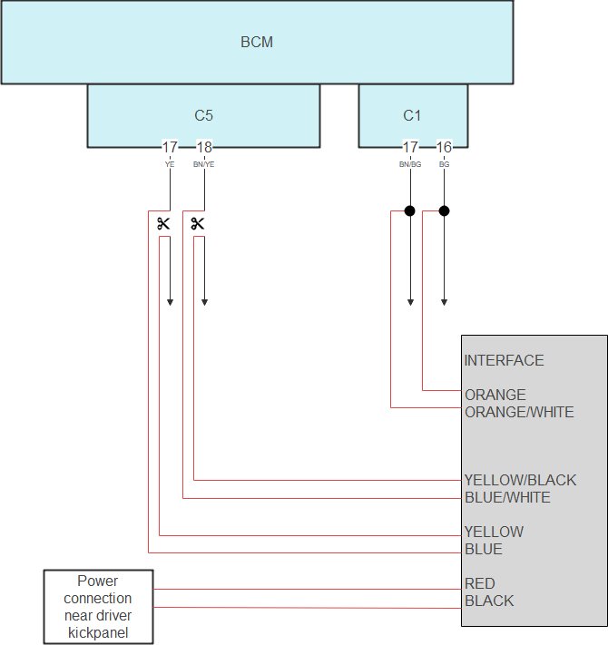
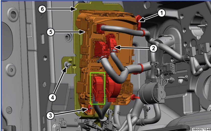
Connect to BCM C1 Plug
Unplug the BCM black C1 plug.
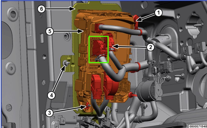
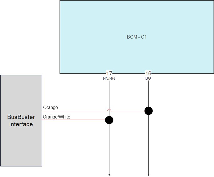
Connect the twisted-pair CAN bus wires from the interface in parallel with the existing wires on pins 16 and 17.
| Interface | BCM plug |
|---|---|
| Orange/White | Pin 17 Brown/Beige |
| Orange | Pin 16 Beige |
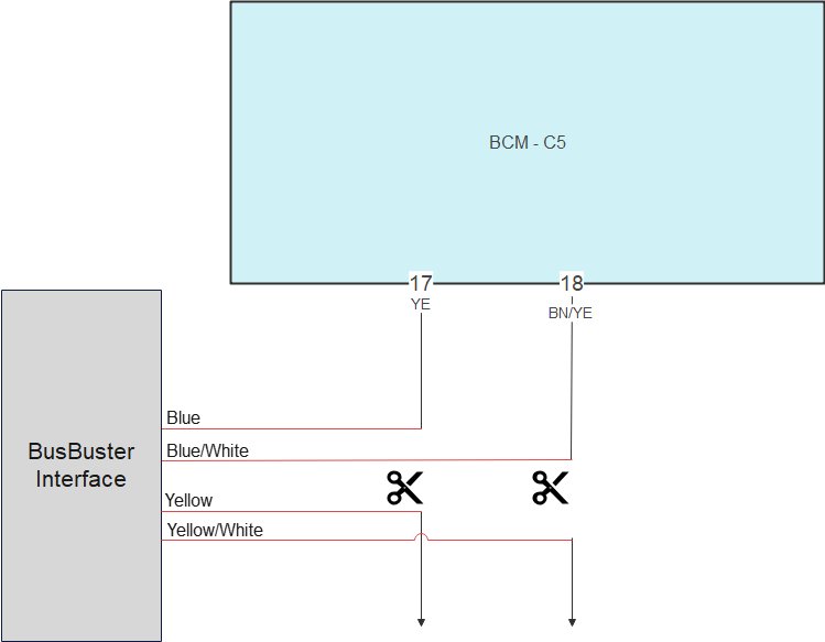
Connect to BCM C5 Plug
Unplug the BCM black C5 plug.
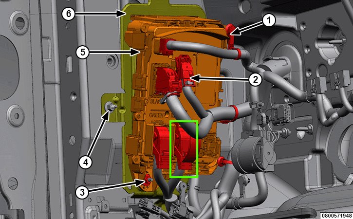
Cut the twisted C1 CAN bus wires and connect the 2 pairs from the interface to the wire ends.
| Interface | BCM plug side | CAR wire side |
|---|---|---|
| Blue | Pin 17 Yellow | |
| Blue/White | Pin 18 Brown/Yellow | |
| Yellow | Yellow | |
| Yellow/Black | Brown/Yellow |
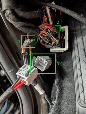
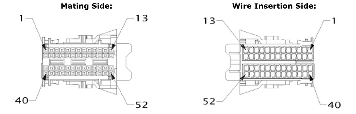
Power Connections in Driver Kickpanel
In the driver kickpanel:
- Connect the black ground wire from the interface.
- Connect the red logic power wire from the interface. Connect in parallel to the top-right red wire on the 59-pin plug, pin 1 (red).
If pin 1 is unused, use pin 2 (red) directly below pin 1. - Plug in the 4-pin cable.
(The connector can be hidden under the carpet.)
For connecting the trailer outputs. => See Trailer Harness
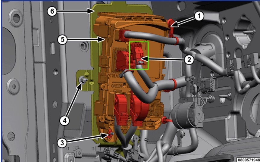
Mount the Interface
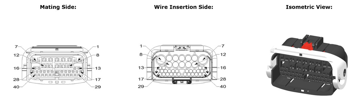
Mount the interface securely and connect both the 6-pin and 16-pin connectors.
Complete BCM Connection Diagram
Complete BCM connection diagram for:
- High Trim
- Low trim, without EU lights modification
Low Trim with EU Lights Modification
Preparation
Start by preparing 3 jumper wires (approx. 35 cm each) and wrap them with cloth tape.
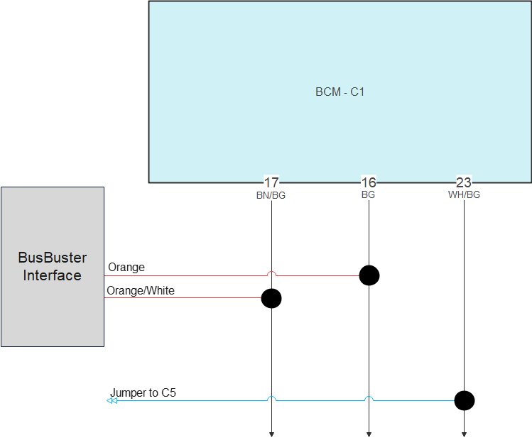
Connect to BCM C1 Plug
Unplug the BCM black C1 plug.
Connect the twisted pair CAN bus wires from the
interface in parallel with the existing wires
on pin 16 and 17.
Connect one end of Jumper 1 in parallel with the existing wire on pin 23.
| Interface | BCM plug |
|---|---|
| Orange/White | Pin 17 Brown/Beige |
| Orange | Pin 16 Beige |
| Jumper 1 | Pin 23 White/Beige |
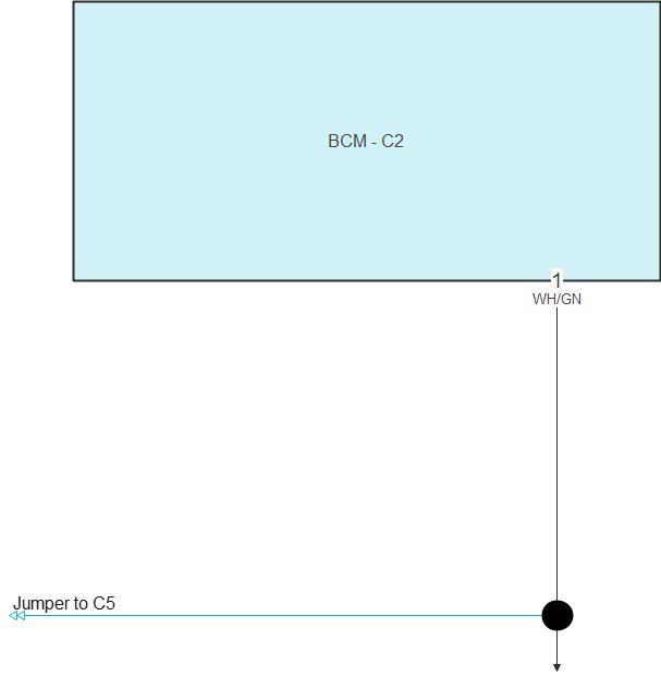
Connect to BCM C2 Plug
Unplug the BCM blue C2 plug.
Connect one end of the jumper wire in parallel with the existing wire on pin 1.
| BCM plug | |
|---|---|
| Jumper 2 | Pin 1 White/Green |
Connect to BCM C6 Plug
Unplug the BCM green C6 plug.
Connect one end of the jumper wire in parallel with the existing wire on pin 1.
| BCM plug | |
|---|---|
| Jumper 3 | Pin 1 Yellow |

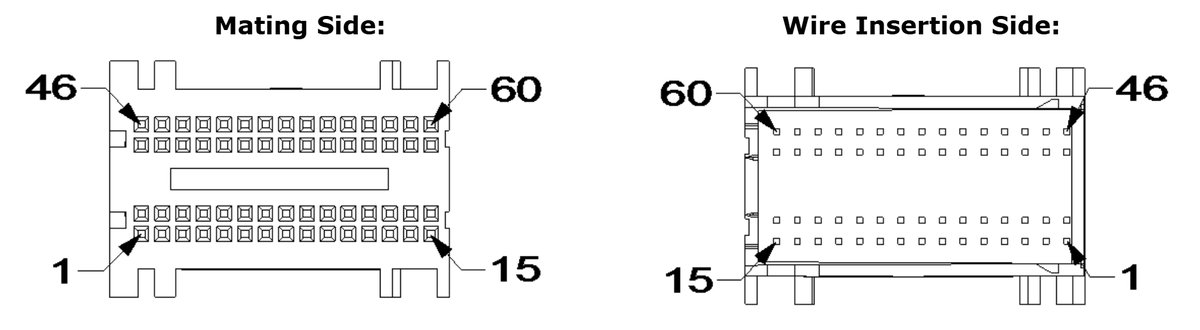
Connect to BCM C5 Plug
Unplug the BCM black C5 plug.
Cut the twisted C1 CAN bus wires and connect the two pairs from the interface to the wire ends.
Connect the grey wire from the interface in parallel with pin 45.
Cut the wire from pin 46. Connect the vehicle-side wire in parallel with the pin 3 wire. Also connect the jumper coming from C6 in parallel with the pin 3 wire.
Cut pins 5 and 7. Connect the vehicle-side wires to the jumpers coming from C1 and C2.
| Interface | BCM plug side | CAR wire side | Parallel on wire |
|---|---|---|---|
| Blue | Pin 17 Yellow | ||
| Blue/White | Pin 18 Brown/Yellow | ||
| Yellow | Yellow | ||
| Yellow/Black | Brown/Yellow | ||
| Grey | Pin 45 White/Blue | ||
| Jumper 1 (C1) | Pin 5 White/Violet | ||
| Jumper 2 (C2) | Pin 7 White/Beige | ||
| Jumper 3 (C6) | Pin 3 White/Beige |
Power Connections in Driver Kickpanel
In the driver kickpanel:
- Connect the black ground wire from the interface.
- Connect the red logic power wire from the interface. Connect in parallel to the top-right red wire on the 59-pin plug, pin 1 (red).
If pin 1 is unused, use pin 2 (red) directly below pin 1. - Plug in the 4-pin cable.
(The connector can be hidden under the carpet.)
For connecting the trailer outputs. => See Trailer Harness
Mount the Interface
Mount the interface securely and connect both the 6-pin and 16-pin connectors.
Bulb Replacement
To comply with BCM limitations and the required light color, the halogen lamps must be replaced with LED bulbs.
| Function | Replace with | Needed for each car |
|---|---|---|
| Brake / Park | Osram 7515DWP-2BL | 4 lamps – 2 packs |
| Turn | Osram 7505DYP-2BL | 2 lamps – 1 pack |
| 3rd Brake | Philips 11067CU31B1 | 1 lamp – 1 pack |
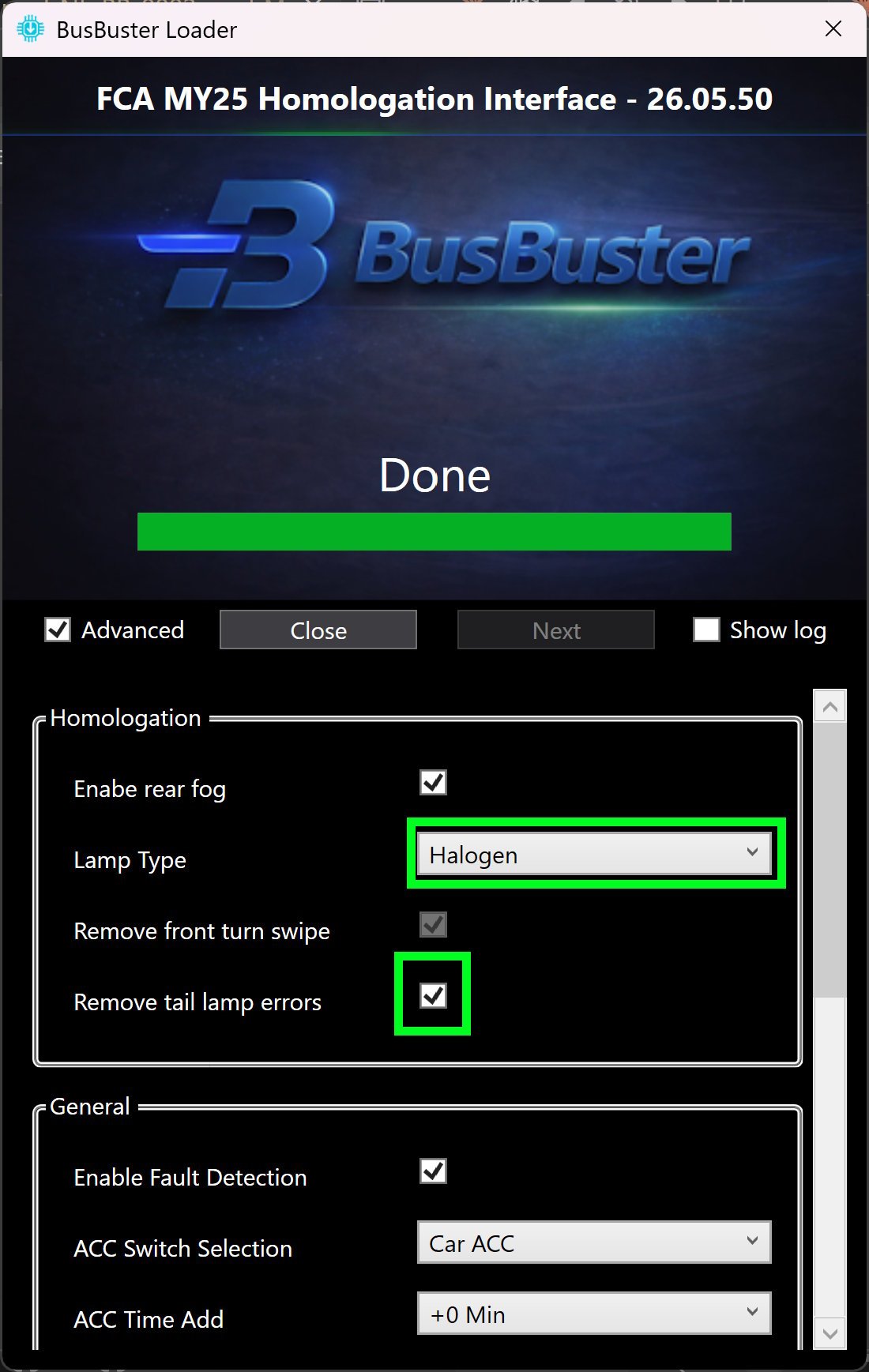
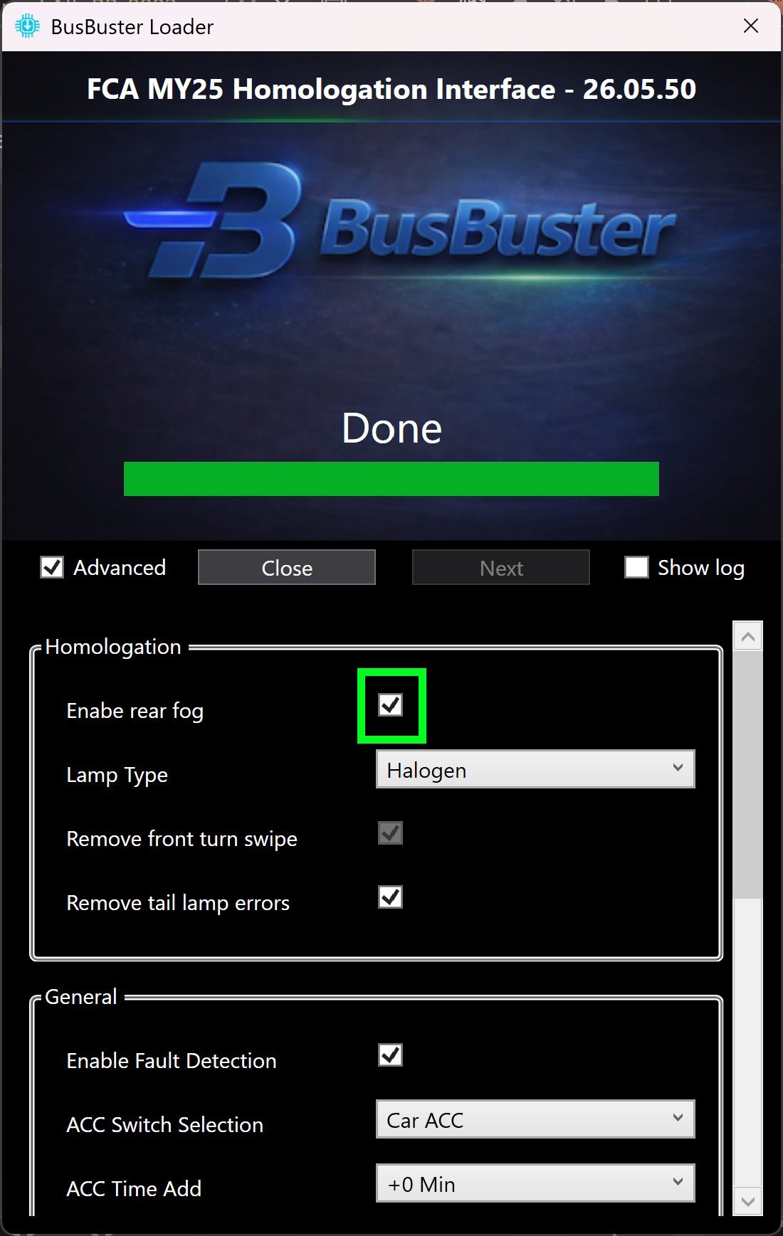
Configuration for EU Lamp Modification
For use with EU lamp modification on halogen models, this setting must be enabled in the interface.
- Start the “BusBuster Loader” program. If there is an update for the interface, it will update it.
- Click on Advanced and agree with the warning.
- Select lamp type: “Halogen”.
- Enable: “Remove tail lamp errors”.
- Optionally also enable “Enable rear fog” to enable rear fog on the OEM light switch if the car does not have this yet.
- Scroll down and click on the “Write” button.
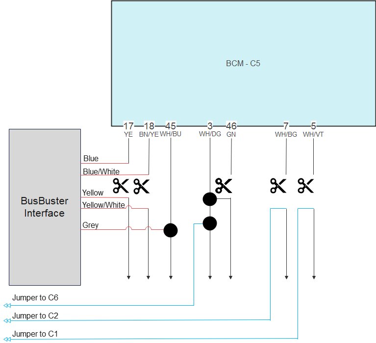
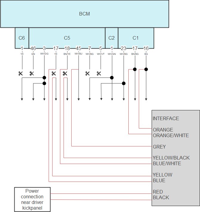
Complete BCM Connection Diagram for EU Lights Mod
Complete BCM connection diagram for:
- Low trim, with EU lights modification
Trailer Harness
The optional trailer harness can significantly reduce installation time.
The harness connects directly to the connector behind the OEM trailer socket.
The other end contains loose pins that can be inserted into the free cavities of the BusBuster connector.
This allows for a fully functional EU trailer socket without cutting or soldering any wires.
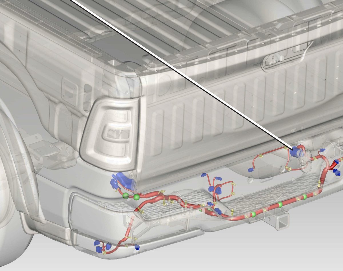
Mounting Trailer Harness
- Unplug the connector from the rear of the OEM trailer socket.
- Connect the trailer harness in between.
- Mount the 13 EU trailer socket.
- Route the cable underneath the rear bench seat,
on the driver side. - Pull the carpeting away from the working area.
- Create an opening in the rubber grommet and feed the cable through.
- Ensure the cable entry is properly sealed and watertight.
- Route the cable to the BusBuster interface near the BCM module.
- Secure the cable properly and keep it away from exhaust heat.
Connecting to BusBuster
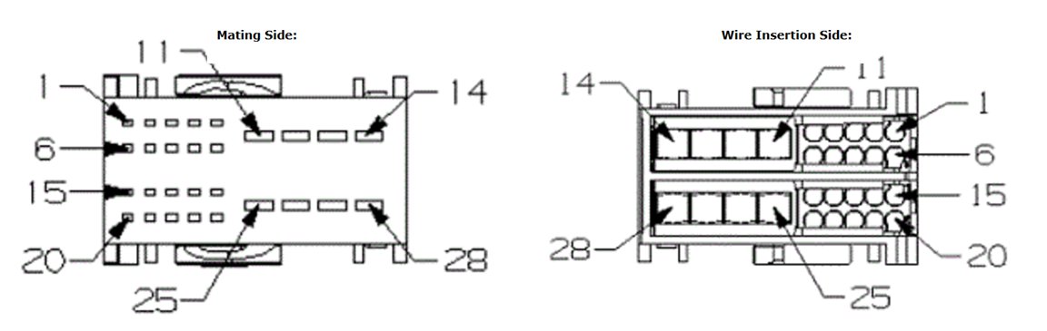
Insert the 4 trailer harness wires into the BusBuster connector as shown below.
| PIN | Color | Function |
|---|---|---|
| 1 | Red* | +12V Input |
| 2 | Grey | Trailer ACC output |
| 3 | Blue | Trailer fog light |
| 4 | Black* | GND input |
| 5 | Yellow | Trailer turn signal (left) |
| 6 | Green | Trailer turn signal (right) |
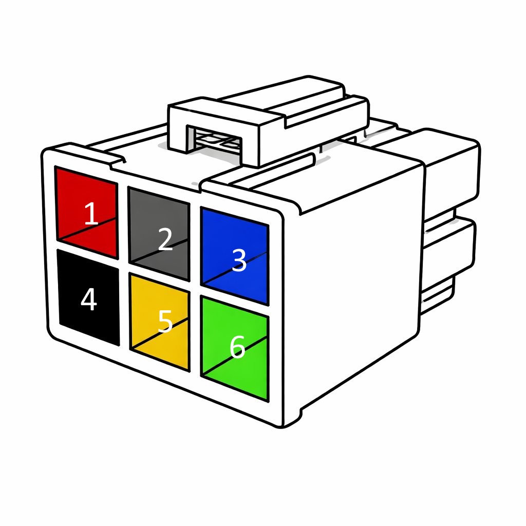
Note:
The red and black wires are pre-installed in the BusBuster connector.
The two additional loose wire outputs near the 7-pin socket provide an output for an additional vehicle reverse light.
This is typically used when the OEM reverse lights are repurposed as turn signals.
If the trailer harness is not used,
the connections can be wired manually.
Terminal P/N: MOLEX 76823-0322.
Enable OEM Rear Fog Control
By enabling this function on cars that do not have rear fog from the factory, you can control the (added) rear fog light using the OEM light switch.
The correct indicators in the cluster will also function.
Configure the interface
- Start the “BusBuster Loader” program. If there is an update for the interface, it will update it.
- Click on Advanced and agree with the warning.
- Enable “Enable rear fog” to enable rear fog on the OEM light switch.
- Scroll down and click on the “Write” button.
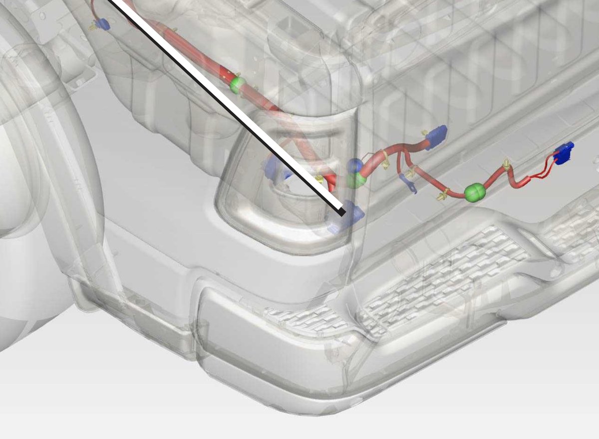
Connect the added rear foglamp
Connect 1 or 2 rear fog lights,
on the wires in the connector behind the bumper.
Both wires must have a load; otherwise an error will be shown.
If you want to add only one lamp, use two diodes to split the load.
| PIN | Color | Function |
|---|---|---|
| 2 | White/Dark-Green | Rear Fog Right |
| 3 | White/Orange | Rear Fog Left |
| 6 | Black | Ground |